Products
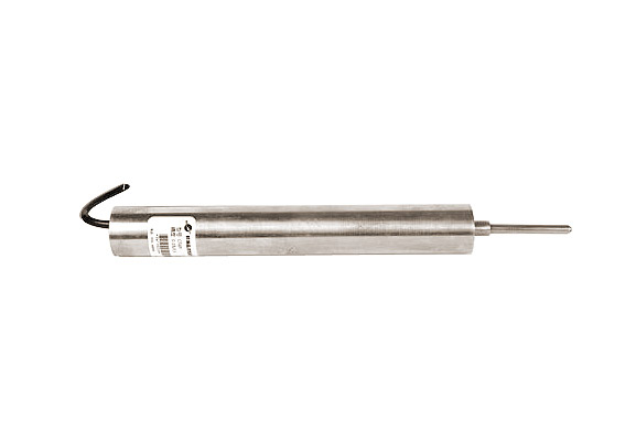
CFWY displacement sensor

Features and Uses
Displacement sensing transducer is a differential pole structure, consisting of leveled excitation signal source, detection circuit and filter amplifier composed of leveled signal source is constituted by an integrated amplifier, high stable sine wave output, so it has stability high, waveform distortion, temperature drift, load capacity, long-term operation and so on. The sensor is divided into spring-and straight pull two. In a standard current or voltage output form accurately reflects the change in position.
Dimensions

Technical Specifications
| Specification | Range (mm) | A (mm) | L (mm) | △ L (mm) | D (mm) | E (mm) | |
| Maximum | Least | ||||||
| 5L, 2.5D | 5, ± 2.5 | 130 | 30 | 54 | 15 | Ф26 | M5 |
| 10L, 5D | 10, ± 5 | 130 | 30 | 80 | 15 | Ф26 | M5 |
| 20L, 10D | 20, ± 10 | 160 | 30 | 95 | 15 | Ф26 | M5 |
| 30L, 15D | 30, ± 15 | 180 | 30 | 111 | 15 | Ф26 | M5 |
| 50L, 25D | 50, ± 25 | 230 | 30 | 155 | 15 | Ф26 | M5 |
| 100L, 50D | 100, ± 50 | 280 | 30 | 205 | 15 | Ф26 | M5 |
| 150L, 75D | 150, ± 75 | 380 | 30 | 265 | 15 | Ф26 | M5 |
| 200L, 100D | 200, ± 100 | 400 | 30 | 321 | 15 | Ф26 | M5 |
| 300L, 150D | 300, ± 150 | 540 | 30 | 485 | 15 | Ф26 | M5 |
| 400L, 200D | 400, ± 200 | 670 | 30 | 644 | 15 | Ф26 | M5 |
| 500L, 250D | 500, ± 250 | 830 | 50 | 749 | 15 | Ф26 | M5 |
| 600L, 300D | 600, ± 300 | 950 | 50 | 749 | 15 | Ф26 | M5 |
| 700L, 350D | 700, ± 350 | 960 | 50 | 791 | 20 | Ф26 | M8 |
| 800L, 400D | 800, ± 400 | 1093 | 50 | 845 | 20 | Ф26 | M8 |
| 900L, 450D | 900, ± 450 | 1242 | 50 | 1004 | 20 | Ф26 | M8 |
| 1000L, 500D | 1000, ± 500 | 1336 | 50 | 1088 | 20 | Ф26 | M8 |
| Overall accuracy | 0.05%, 0.1%, 0.5%, 1% F · S | ||||||
| Output Signal | 4 ~ 20mA, 0 ~ 5V or 0 ~ ± 5V, 0 ~ ± 10V | ||||||
| Supply Voltage | 12V, 24VDC (standard) | ||||||
| Operating Temperature | -10 ~ 60 ℃ | ||||||
| Zero drift | 0.01% / ℃ | ||||||
| Sensitivity drift | 0.05% / ℃ | ||||||
| Dynamic Frequency | 0 ~ 200Hz | ||||||
Installation methods
Rod displacement sensor can be mounted horizontally and vertically mounted, first put the sensor object reference (baseline) of the mounting bracket, the sensor rod and the measured object moving in the same direction, according to the sensor range, estimated at roughly the gap , and then use the lever and nut analyte fixed up and pass on the power supply and other sensors to stabilize, slowly moving the sensor housing, the sensor output is zero corresponds to the analyte mechanical zero, then the sensor housing clamp (non-loose), it can be installed on the test computer data acquisition displacement of objects seized control or PLC control system, rebound displacement sensors and displacement sensors mounted rod basically similar.
Precautions
1, is careful not to install the sensor core and measuring rod by two large lateral forces caused by bending, otherwise it will seriously affect the measuring rod activity flexibility. Sensor housing is a high permeability material, should avoid falling and by the impact.
2, the sensor measuring rod (head) should be consistent with the moving direction of the measured object, better concentricity. Rebound displacement sensor in contact with the measured object should have a certain finish plane, uneven affect measurement accuracy.
3, the sensor is a cross section of the work spindle are generally in the middle portion of the active region. Measuring rod fully extended and fully compressed in the vicinity of segments are non-active area. Install the sensor is to be adjusted (move) the sensor housing, according to rough estimates range clearance. The displacement within the predetermined range, you can also use a digital voltmeter aligning electrical zero position, and then tested.
4, the external positive and negative power supply is recommended using a linear power supply. If using switching power supply, signal output of the clutter (interference) voltage will be increased significantly. Each board is not greater than the actual consumption mA. (However, the actual supply should be left margin, it is best not less than 50mA)
5, if found by the measuring rod adhesions caused by dust or oil activities astringent, cotton with alcohol wipe, clean measuring rod, but please do not disassemble the sensor to avoid damage or reduce the measurement accuracy.


